


MTW European Type Trapezium Mill
Input size:30-50mm
Capacity: 3-50t/h
LM Vertical Roller Mill
Input size:38-65mm
Capacity: 13-70t/h
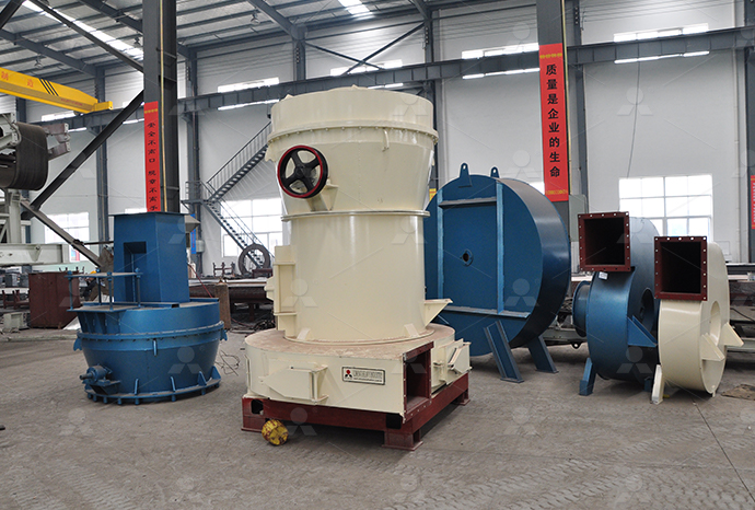
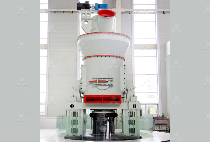
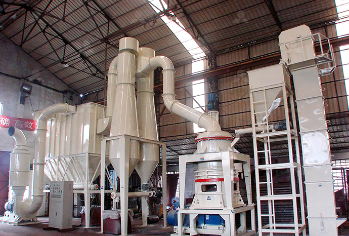
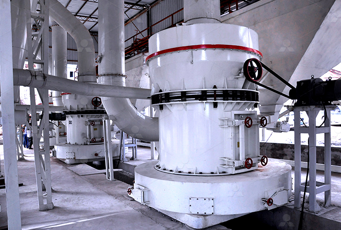
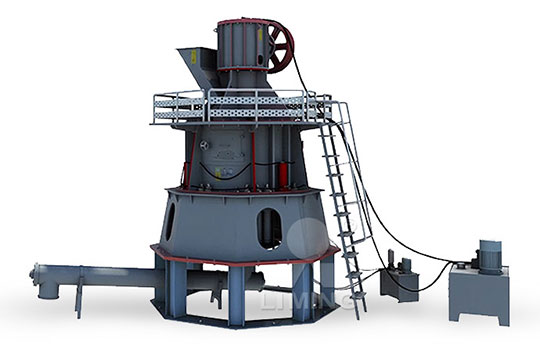
Raymond Mill
Input size:20-30mm
Capacity: 0.8-9.5t/h

Sand powder vertical mill
Input size:30-55mm
Capacity: 30-900t/h

LUM series superfine vertical roller grinding mill
Input size:10-20mm
Capacity: 5-18t/h
MW Micro Powder Mill
Input size:≤20mm
Capacity: 0.5-12t/h

LM Vertical Slag Mill
Input size:38-65mm
Capacity: 7-100t/h

LM Vertical Coal Mill
Input size:≤50mm
Capacity: 5-100t/h
TGM Trapezium Mill
Input size:25-40mm
Capacity: 3-36t/h

MB5X Pendulum Roller Grinding Mill
Input size:25-55mm
Capacity: 4-100t/h
Straight-Through Centrifugal Mill
Input size:30-40mm
Capacity: 15-45t/h
Fourroller hydraulic station automatic control schematic diagram

Structure diagram of fourhigh load roll system
In the metallurgical industry, hydraulic automatic gauge control (HAGC) is a core mechanism for thickness control of plates used in the rolling process The stability of the HAGC system’sAll hydraulic units and their connections must be shown on the circuit diagram The hydraulic schematic forms the basis of the pipework of the system and –– together with the function Circuit diagram HAWE Hydraulik•The development of the control system solution requires that the problem is defined clearly •There are many ways of representing the problem in a descriptive or graphical form The Pneumatics and Hydraulics Philadelphia UniversityControl of a hydraulic system may range from the simple starting and stopping of the system to controlling extension and retraction of several cylinders in a completely automated factory A Unit Introduction to Electrical Control of Hydraulic Systems
The Ultimate Guide to Understanding Schematic Diagrams of
Understanding the schematic diagram of a hydraulic system is essential for designing, constructing, and maintaining hydraulic systems It allows technicians to identify and locate Typical hydraulic circuits for control of industrial machinery are described in this lesson Graphical hydraulic circuit diagrams incorporating component symbols are used to explain the operation INDUSTRIAL HYDRAULIC CIRCUITS IDCOnlineDiscuss the advantages and disadvantages of representing hydraulic components using pictorial, cutaway, and schematic symbols Differentiate between working, pilot, and drain lines and 29 Hydraulic Schematics – Hydraulics and Electrical Control of The new system design has been developed to operate using a Hydraulic Power pack source, where it consists of four hydraulic wheel hubs for driving the system, four hydraulic cylindersElectro hydraulic system schematic diagram
Design and development of high precision four roll CNC roll
2023年8月10日 Based on this, this study verifies the rationality of the application of servo electric cylinders in a bending machine, and uses profile forming curve (R) and servo electric cylinder • Interpret hydraulic system symbols and circuit diagrams • Describe techniques for energy saving in hydraulic systems Introduction Typical hydraulic circuits for control of industrial machinery are described in this lesson Graphical hydraulic circuit diagrams incorporating component symbols are used to explain the operation of the circuitsINDUSTRIAL HYDRAULIC CIRCUITS IDCOnlineHydraulic schematic symbols are standardized graphical representations used to depict the components of hydraulic systems on schematic diagrams These symbols allow engineers, indicating their function to regulate or limit Hydraulic Schematic Symbols : How To Read A Define a hydraulic motor Draw the schematic symbol Define a hydraulic cylinder Draw the schematic symbol for a double acting hydraulic cylinder, a hydraulically extended spring retracted single acting cylinder, a spring extended hydraulically retracted single acting cylinder, and single acting ram Discuss how these cylinders extend and retract29 Hydraulic Schematics – Hydraulics and Electrical Control of

Hydraulic schematic Hydraulic circuits Mechanical Engineering
"Hydraulics is a topic in applied science and engineering dealing with the mechanical properties of liquids At a very basic level hydraulics is the liquid version of pneumatics Fluid mechanics provides the theoretical foundation for hydraulics, which focuses on the engineering uses of fluid properties In fluid power, hydraulics is used for the generation, control, and transmission of Download scientific diagram Hydraulic schematic diagram of the eightspeed automatic transmission from publication: A method of applying twopump system in automatic transmissions for energy Hydraulic schematic diagram of the eightspeed automatic 2016年3月21日 In Figure 2B (a 3position valve), the valve has both solenoids and ‘spring return’ actuators on both sides, the spring return actuators will return the valve to the center position but only IF neither of the solenoids is active: With this 3position valve, the center flow box shows the flow path when neither actuator is active and the springs are holding the valve in the center Pneumatic Circuit Symbols ExplainedDownload scientific diagram Schematic diagram of the servo valve control hydraulic cylinder from publication: Absolute Stability Condition Derivation for Position ClosedLoop System in Schematic diagram of the servo valve control hydraulic cylinder

Lecture 24 HYDRAULIC CIRCUIT DESIGN AND ANALYSIS
Calculate the speed, pressure and loadcarrying capacity of hydraulic circuits Evaluate the performance of hydraulic circuits using various hydraulic elements 11 Introduction A hydraulic circuit is a group of components such as pumps, actuators, control valves, conductors and fittings arranged to perform useful workDownload scientific diagram Schematic diagram of a hydraulic clutch control unit from publication: Dynamic Analysis and Control of the Clutch Filling Process in ClutchtoClutch Transmissions Schematic diagram of a hydraulic clutch control unitDiagramming Build diagrams of all kinds from flowcharts to floor plans with intuitive tools and templates Whiteboarding Collaborate with your team on a seamless workspace no matter where they are Data Generate diagrams from data and add data to shapes to enhance your existing visuals Enterprise Friendly Easy to administer and license your entire organizationSchematic Diagram Maker Free Online App SmartDrawTypical Wiring Diagrams For Push Button Control Stations 3 Genera/ Information @ Each circuit is illustrated with a control circuit (continued) schematic or line diagram and a control station wiring diagram l The schematic or line diagram includes all the components of the control circuit and indicates their80020 Typical Wiring Diagrams for Push Button Control Stations
.jpg)
Circuit diagram HAWE Hydraulik
HAWE Hydraulik develops and produces hydraulic components and systems for mechanical and plant engineering Contact; Customer All hydraulic units and their connections must be shown on the circuit diagram The hydraulic schematic forms the basis of the pipework of the system and –– together with the function diagram — forms "Directional control valves are one of the most fundamental parts in hydraulic machinery as well and pneumatic machinery They allow fluid flow into different paths from one or more sources They usually consist of a spool inside a cylinder which is mechanically or electrically controlled The movement of the spool restricts or permits the flow, thus it controls the fluid flow" Directional control valve Hydraulic 4ported 3position valve Download scientific diagram Schematic diagram of hydraulic transmission system 1 − Gasoline engine, 2 − Speed sensor, 3 − Pump servo cylinder, 4 − NFPE Proportional electromagnetic Schematic diagram of hydraulic transmission system 1 − A hydraulic system can be controlled either manually or automatically: C Manual control: system operation is sequenced and commanded by an operator that decides each action to take C Automatic control: system operation is sequenced and commanded by a controller that decides each action to take Automatic control can be accomplished by means of:Unit Introduction to Electrical Control of Hydraulic Systems
Schematic diagram of the hydraulic system of the constant
Download scientific diagram Schematic diagram of the hydraulic system of the constant deceleration compensation 1 Twoposition fourway reversing valve; 2 Stop valve; 3 Pressure transmitter Download scientific diagram Schematic diagram of the hydraulic system 1: oil tank, 2: ball valve, 3: strainer, 4: proportional relief valve, 5: proportional pump Figure 1 Schematic diagram of the hydraulic system 1: oil tank, Download scientific diagram Schematic diagram of hydraulic system of wet dual clutch automatic transmission from publication: Hydraulic System Optimization and Dynamic Characteristic Simulation Schematic diagram of hydraulic system of wet dual clutch automatic Following are schematic symbols for commonly used directional control valves 2way directional control valves A 2way directional valve has two ports normally called inlet and outlet When the inlet is blocked in the atrest condition, as shown in Figure 8 BOOK 2, CHAPTER 8: Directional Control Valves Power Motion

Schematic diagram of clutch hydraulic control system
Download scientific diagram Schematic diagram of clutch hydraulic control system from publication: Study on the Shifting Quality of the CVT Tractor under Hydraulic System Failure The failure A Piping Instrumentation Diagram (PID) is a schematic layout of a plant that displays the units to be used, the pipes connecting these units, and the sensors and control valves Standard 43: Piping and Instrumentation Diagrams 43: Piping and Instrumentation DiagramsThe power system of automatic control: Oil terminal and hydraulic pressure station system startup conditions meet can start roller mill power systems Vertical mill power system includes main motor,Design and Realization Of Roller Mill Control SystemBOMAG BW 2123 Single Drum Vibratory Roller Hydraulic Schematics and Circuit Diagrams Manual What's , speedometer 007 582 700 86 Fahren, Bremse, Fahrstufen driving, brake, speed ranges 008 582 700 86 Vibration, Speed Control the BOMAG BW 2123 Single Drum Vibratory Roller Hydraulic Schematics and Circuit Diagrams Workshop BOMAG BW 2123 Single Drum Vibratory Roller Hydraulic Schematics and
.jpg)
Control of a DoubleActing Hydraulic Cylinder
2019年5月12日 Control of a DoubleActing Hydraulic Cylinder The circuit diagram to control doubleacting cylinder is shown in Fig 12 The control of a doubleacting hydraulic cylinder is described as follows: 1 When the 4/3 valve is in its neutral position (tandem design), the cylinder is hydraulically locked and the pump is unloaded back to the tank 2Download scientific diagram Schematic diagram (a), closedloop position control system (b) and view (c) of a integrated electrohydraulic servodrive (IEHSD): 1 hydraulic actuator, 2 Schematic diagram (a), closedloop position control system (b) Hydraulic Schematics and Basic Circuit Design provides an overview of basic hydraulic circuit configurations and the standard fluid symbols in fluid schematic diagrams A hydraulic schematic diagram uses lines and symbols to provide a visual display of fluid paths within a hydraulic circuit A hydraulic schematic also indicates the types and capabilities of components in the circuit Hydraulic Schematics and Basic Circuit Design 342 Tooling USMEHowever, knowledge about relay logic and ladder diagrams is very useful Ladder Diagram Symbols Ladder diagrams differ from regular schematic diagrams of the sort common to electronics technicians primarily in the strict orientation of the wiring: vertical power “rails” and horizontal control “rungs”Relay Circuits and Ladder Diagrams Control
.jpg)
Schematic diagram of hydraulic press machine emulator
Download scientific diagram Schematic diagram of hydraulic press machine emulator from publication: Control of Hardware Implementation of Hydraulic Servo Application Based on Adaptive Neuro The Lippert Hydraulic Slideout System is a rack pinion guide system, utilizing a hydraulic actuator to move the room assembly The power unite drives the cylinder rod in a forward and backward motion to drive the slide room in and out The Lippert Hydraulic Slideout System is designed to operate as a negative ground system 3 PRIOR TO OPERATIONHYDRAULIC SLIDEOUT SYSTEM OPERATION AND SERVICE 2019年6月5日 2 Schematic shows simple circuit to control cylinder extension and retraction using a 4port, 3position spool valve Spooltype valves are widely used because they can be shifted to two, three, or more positions for routing fluid between different combinations of Basics of DirectionalControl Valves Power Motionautomatic realtime control, designed specifically for industrial control of the computer, in line with industrial environmental requirements It is a combination of automatic control technology and computer technology into automatic control products Widely used in all areas of current industrial control The robot controlDesign of control and hydraulic drive system
.jpg)
Schematic diagram of a fourhigh mill stand
Download scientific diagram Schematic diagram of a fourhigh mill stand from publication: Automatic control of mechatronic systems This contribution deals with different concepts of nonlinear 2024年8月4日 Fig3 80,000 Ton Die Forging Press The 80,000ton dieforging hydraulic press stands 27 meters tall on the ground and 15 meters underground, making it a total height of 42 meters and a total weight of 22,000 tons, thereby Hydraulic Press Machine 101: Everything You Need to Download scientific diagram Schematic diagram of hydraulic cylinder structure from publication: Modeling and Analysis on Cushion Characteristics of Fast and HighFlowRate Hydraulic Cylinder Schematic diagram of hydraulic cylinder structureDownload scientific diagram Schematic diagram of the hydraulic braking system from publication: Modeswitchingbased active control of powertrain system with nonlinear backlash and flexibility Schematic diagram of the hydraulic braking system
(PDF) Automatic Railway Gate Control Hydraulic Road System
2023年1月14日 Arduino UNO), hydraulic road control system, automatic gate control system and tra in system We design to use infrared (IR) sensors to operate the railway crossing s ystems which will be However, the primary control is the prime mover or turbine control achieved through a speed governor which regulates the active power along with the frequency by regulating the turbinegenerator Simplified schematic of a hydroelectric power plantDownload scientific diagram Schematic diagram of the hydraulic drive circuit from publication: Analysis of the characteristics of electromechanicalhydraulic model of multisource drive Schematic diagram of the hydraulic drive circuit2007年2月8日 Fig 1025 Doublesolenoid, 3position, pilotoperated, springcentered, 4way directional control valve The cutaway view in Figure 1025 represents a solenoid pilotoperated valve with an allportsopen center condition These larger, highflow valves operate in the same way and perform the same functions as the direct solenoidoperated valves discussed earlierCHAPTER 10: Directional Control Valves, part 4 Power Motion
The Role and Value of Hydraulic Schematic Diagrams
2023年12月18日 The first is to conduct a visual inspection of the hydraulic system, checking all the easy things that could cause the problem in question (never overlook the obvious) The second is to ask for the schematic diagram for the machine’s hydraulic circuit A schematic diagram is a ‘road map’ of the hydraulic system