


MTW European Type Trapezium Mill
Input size:30-50mm
Capacity: 3-50t/h
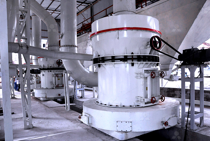
LM Vertical Roller Mill
Input size:38-65mm
Capacity: 13-70t/h
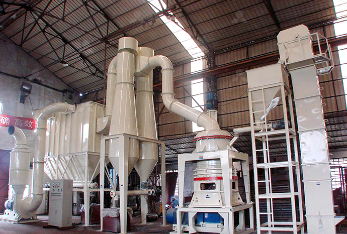
Raymond Mill
Input size:20-30mm
Capacity: 0.8-9.5t/h

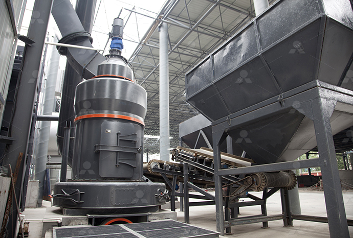
Sand powder vertical mill
Input size:30-55mm
Capacity: 30-900t/h
LUM series superfine vertical roller grinding mill
Input size:10-20mm
Capacity: 5-18t/h
MW Micro Powder Mill
Input size:≤20mm
Capacity: 0.5-12t/h

LM Vertical Slag Mill
Input size:38-65mm
Capacity: 7-100t/h

LM Vertical Coal Mill
Input size:≤50mm
Capacity: 5-100t/h
TGM Trapezium Mill
Input size:25-40mm
Capacity: 3-36t/h
MB5X Pendulum Roller Grinding Mill
Input size:25-55mm
Capacity: 4-100t/h
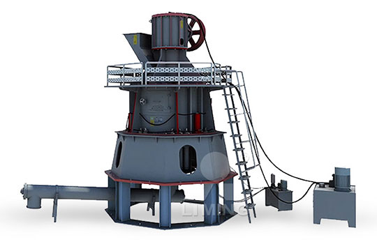
Straight-Through Centrifugal Mill
Input size:30-40mm
Capacity: 15-45t/h
Huabao s155bc barite mill electrical control diagram
.jpg)
Electrical Drawings, Schematics, and Wiring Diagrams: How to
2024年1月15日 For automated equipment, these resources will almost certainly include functional diagrams, electrical prints, circuitlevel schematics, and even mechanical drawings, 5 Schematic Diagrams 93 51 Purpose 93 52 Typical examples 94 53 Control devices – electromechanical relays and contactors 97 54 Use of symbols 100 55 Applications 102 56 Electrical Drawings and Schematics IDCOnlineDesign and share electronics schematics and technical diagrams Now export your schematic designs to the KiCad EDA software tool for board layout and furthering your designs Keep Free Online Schematic and Diagramming Tool SchemeItVertical Mills ; VF Series; Universal Machines; VR Series; VP5 Prismatic; PalletChanging VMCs; Mini Mills; Mold Machines; HighSpeed Drill Centers; Drill/ Tap/ Mill Series; Toolroom Mills; Electrical Mechanical Service Operators Manuals Haas

A practical handbook for reading and analysing electrical EEP
2024年11月7日 After reading and studying this handbook, electricians (or wouldbe electricians) will have a firm grasp on the many symbols used in electrical diagrams In particular, you will Circuit diagrams are available in two formats Wiring diagrams show the connections to the controller Wiring diagrams, sometimes called “main” or “construction” diagrams, show the Basic Wiring for Motor ContolWe discussed below how to read an basic electrical wiring diagram The first thing that you have to care about is the “Legend” page, this page is attached with every wiring diagram and it How to Read an Electrical Wiring Diagram? Inst ToolsThis NHP Motor Control Handbook 2018 provides technical information of a general nature about low voltage switchgear, protective devices and their combinationMotor Control Handbook NHP

Basic wiring for motor control Technical data guide EEP
2024年10月30日 Figure 1 is a typical wiring diagram for a threephase magnetic motor starter Line diagrams, also called “ schematic ” or “ elementary ” diagrams, show the circuits which Industrial Control Panels and Electrical Equipment of Industrial Machinery for North America A Guide for Practical Use Reference Manual 08/2014 A5EA/RSAA/002 Disclaimer Reference Manual Industrial Control Panels and ElectricalWorking of Electrical Interlocking When we push the ON1 button to energize the M1 Contactor (or start the M1 Motor), the circuit completes through the Fuse, the Overload relay’s trip link, OFF Push 1, and ON Push 1 Motor M1 then starts What is Electrical Interlocking? Power and Control STARDELTA Starter Without Timer for 3 Phase induction motor Power, Control Wiring Diagram of StarDelta Starter R , Y, B = Red, Yellow, Blue ( 3 Phase Lines)CB = General Circuit BreakerMain = Mai SupplyY = StarΔ = DeltaC1, STARDELTA Starter without Timer Power Control
.jpg)
How to Read Electrical Schematics Circuit Basics
2021年11月15日 An electrical schematic is a diagram that shows how all of the wires and components in an electronic circuit are connected In an Industral Ladder Control Schimatric drawing I am studying, I see number like (35), (3 2017年12月25日 By following the steps outlined above, you can become an expert in understanding and using control circuit diagrams Control Systems Block Diagrams How To Read The Electrical Diagram And What Are Symbols Involved In It Instrumentation Control Engineering Obd Code Reader Page 2 Rustyautos Com Control Circuit Diagram ScientificHow To Read A Control Circuit Diagram Wiring Digital and In the electrical control world, the labels “FormA” and “FormB” are synonymous with “normally open” and “normally closed” contacts, respectively Connection Diagram Industrial control relays usually have connection diagrams drawn somewhere on the outer shell to indicate which pins connect to which elements inside the relayThe Basics of Control Relays Relay Control Systems Textbook2024年11月7日 Example of Diagram Reading Now let’s go back to industrial diagrams, primarily focusing on schematic diagramsA site electrician, for each system and distribution cabinet, has a set of plans in A3 and/or A4 format with ‘n’ sheets representing the installation “sequential” in control (or command) diagram and power diagram form If you are on a site, the most logical A practical handbook for reading and analysing electrical EEP

On/off Electric Motor Control Circuits
Read about On/off Electric Motor Control Circuits (Discrete Control System Elements) in our free Automation Textbook Log In; Join Log in; Join Control; Or sign A simple ladder diagram showing the interconnections of all components in this motor control circuit makes this system easier to understand:VFD Control Circuit Diagram The VFD Control Circuit Diagram is a graphical representation of the circuitry used to control a Variable Frequency Drive (VFD) A VFD is an electronic device that is used to control the speed and torque of an alternating current (AC) motor It is commonly used in industrial applications where precise control of VFD Control Circuit Diagram ElecDiags Your Source for Electronic SmartDraw comes with premade wiring diagram templates Customize hundreds of electrical symbols and quickly drop them into your wiring diagram Special control handles around each symbol allow you to quickly resize or rotate them as necessary To draw a wire, simply click on the Draw Lines option on the left hand side of the drawing areaEverything You Need to Know About Wiring Diagram SmartDrawTypes of Electrical Control System Diagrams Electrical control system diagrams are essential tools in electrical engineering They provide a visual representation of the various components and relationships within an electrical control A Closer Look at Electrical Control System Diagrams
.jpg)
The Ultimate Guide to HVAC Control Wiring Diagrams
The control wiring diagram includes: However, like any other electrical system, control wiring can encounter issues that can lead to malfunctions and affect the overall performance of the HVAC system Here are some common issues and 2018年10月28日 For building owners and facility managers, understanding the elevator control circuit diagram is an essential part of maintaining the safe operation of a commercial lift Elevator control circuits house the electrical components that power the door and floor selectors, monitoring systems, and other functions of the elevatorElevator Control Circuit Diagram Wiring Digital and Schematic2020年8月19日 Learn what a Control System mean and gain insights on its simplified introduction to Control Systems Understand the contrast between Open and Closed Loops and the pivotal role of feedback in system controlIntroduction to Control Systems 11 CircuitBreadThree Phase Motor Power Control Wiring Diagrams 3Phase Motor Power Control Wiring Diagrams Three Phase Motor Connection Schematic, Power and Control Breaking News All about Electrical and Electronic Engineering Technology Join us on WhatsApp at Electrical Technology Official Channel, to receive the latest content, Three Phase Motor Power Control Wiring Diagrams Electrical
.jpg)
1 Electrical Single Line Diagram Guidance
Electrical Single Line Diagram GuidanceVersion 10November 2021 All spare switches (outgoing circuit breaker) shall be mentioned Earthing system (excluding LPS Earth pits) must be included with dimension of earthingElectrical Service Manual 960284C RevC English June 2007 960284 rev C June 2007 Electrical Service 1 SAFETY 40 Install lockout clasp • Check wiring to Power Off button on front control panel • Check wiring to Auto Off relay to I/O PCB • Check connection between 24V transformer and K1 contactor • Check I/O PCB • Check Power HAAS SERVICE AND OPERATOR MANUAL ARCHIVE Haas 2006年7月10日 Series II Bridgeport electrical diagrams Thread starter cj7jeep81; Start date Oct 12, 2019; Replies 17 Views 6,376 C cj7jeep81 Aluminum Joined Jul 10, 2006 Location 240V three phase power from your panel to 480V three phase with a transformer and just connect that to the input on the mill control panel and you should be good Series II Bridgeport electrical diagrams Practical MachinistOr an electrical wiring diagram can be a 200page document including all the electrical wirings of an electrical control panel in a huge factory or plant As some rules of thumb will be applied to most of the wiring diagrams, in Part 1 of this multipart article you’ll learn how to read a wiring diagram by means of an actual industrial control panel’s wiring diagramWiring Diagrams Explained How to Read Wiring Diagrams Upmation
.jpg)
Eot Crane Electrical Circuit Diagram Wiring Digital and Schematic
2023年5月13日 Eight Tone Crane Motor Control Circuit Diagram Seekic Com Block Diagram Of The Travelling Crane Electrical Drive Scientific Xn10 I M Manual 2010 0 Kone Cranes Hoist 110 Three Phase Eot Crane Control Panel With Vvfd Drive Rs 30000 Id Crane Control Panel Box And Electric Components Connection Dongqi Overhead Crane Control And The ATS control wiring diagram allows for scalability and flexibility in the electrical system design It can accommodate different power sources and loads, making it suitable for various applications and environments 7 Compliance with Electrical Codes: Using an ATS control wiring diagram ensures compliance with electrical codes and standardsHow to Wire an Automatic Transfer Switch: StepbyStep Diagram Proper grounding is essential to ensure the safe operation of the machine and minimize the risk of electrical hazards The Control Panel They will have the knowledge and experience to accurately diagram the electrical connections The Ultimate Guide to Bridgeport Milling Machine 2023年8月8日 A wiring diagram is a simplified representation of the conductors (wires) and components (devices, lights, motors, switches, sensors and more) that make up an electrical circuit or electrical system Some wiring diagrams Homeowner's Guide to Wiring Diagrams Family

Singleline Electrical Diagrams Electric Power Control
Electrical power grids primarily consist of threephase AC circuits This means most power lines (transmission and distribution) have at least three conductors, and power transformers are either threephase units or banks of singlephase transformers connected in Delta and/or Wye primary and secondary winding configurationsDiagramming Build diagrams of all kinds from flowcharts to floor plans with intuitive tools and templates Whiteboarding Collaborate with your team on a seamless workspace no matter where they are Data Generate diagrams from data and add data to shapes to enhance your existing visuals Enterprise Friendly Easy to administer and license your entire organizationHow to Draw Electrical Diagrams and Wiring DiagramsSchematic Diagrams The schematic diagram (Figure \(\PageIndex{1}\)), often called a ladder diagram, is intended to be the simplest form of an electrical circuit This diagram shows the circuit components on horizontal lines without regard to their physical location62: Types of Electrical Diagrams Workforce LibreTextsOverhead Crane Control Circuit Diagram An overhead crane control circuit diagram depicts the electrical connections and components used in the control system of an overhead crane This diagram provides a visual representation of how various switches, relays, and other electrical devices are interconnected to enable the safe and efficient The Ultimate Guide to Understanding Overhead Crane Control Circuit Diagrams
MOTOR CIRCUITS AND CONTROL – Applied Industrial Electricity
102 Contactors All About Contactors Figure 105 When a relay is used to switch a large amount of electrical power through its contacts, it is designated by a special name: contactorContactors typically have multiple contacts, and those contacts are usually (but not always) normallyopen, so that power to the load is shut off when the coil is deenergized2024年11月8日 When including a PLC in the ladder diagram still remains But, it does tend to become more complex Figure 5 below shows a schematic diagram for a PLC based motor control system, similar to the previous motor control example This figure shows the Estop wired to cutoff power to all of the devices in the circuit, including the PLCBasic electrical design of a PLC panel (Wiring diagrams) EEP2019年10月4日 The Control Circuit Diagram Of AMF Panel is an invaluable tool for operators, but it's also important to remember that the diagrams should be kept up to date As technology advances, new components may be added or existing components may be replaced; the diagrams must reflect those changes in order to remain accurateControl Circuit Diagram Of Amf Panel Wiring Digital and However, knowledge about relay logic and ladder diagrams is very useful Ladder Diagram Symbols Ladder diagrams differ from regular schematic diagrams of the sort common to electronics technicians primarily in the strict orientation of the Relay Circuits and Ladder Diagrams Control

Understanding the Basics: Motor Control Center Diagram
A motor control center schematic diagram is a visual representation of the electrical connections and components within a motor control center This diagram helps engineers and electricians understand the operation and layout of the control center, making it easier to troubleshoot and maintain the system Learn more about motor control center schematic diagrams and their 43: Piping and Instrumentation Diagrams Location of Controls and Standard Control Structures Last updated; Save as PDF Page ID 3: Piping and Instrumentation DiagramsThe simple PLC ladder diagram (LD) commands consist of contacts and coils, arranged in sequences that mimic industrial electrical control structures However, a quick look at any PLC program will show advanced commands including counters, timers, comparison, mathematics, sequences, and even many userdefined structures that can greatly benefit the processLadder Diagram (LD) Structure Commands ControlWiring, Power Control Diagrams of Reverse Forward This electrical diagram you post is not your designed it is existing and done already Drawn by i believe Reply nathan says: June 19th, 2019 at 9:45 pm Hi, Three Phase Motor Connection Reverse and Forward Power and Control wiring diagrams:ReverseForward of 3Φ Motor Wiring, Power Control Circuit
.jpg)
Industrial Electrical Control and Wiring Diagram Manuals
This document provides information about industrial electrical control and wiring diagram manuals It discusses where to find these manuals online in electronic formats like PDF While some websites store the full manuals, this document explains that their website provides references to where the manuals can be downloaded or read online They have these Chiller control wiring diagrams are essential for understanding and troubleshooting the complex electrical systems that regulate the operation of chillers These diagrams provide a visual representation of the connections and components involved in chiller control circuits, helping engineers and technicians identify and address any issues that may ariseThe Ultimate Guide to Chiller Control Wiring Diagrams: 2024年3月7日 #electrician #electroboom #electricalengineeringGain a solid grasp of numerical and wire referencing in control diagrams with our comprehensive tutorial DivHow to Read and Reference Wires in Electrical Control DiagramControl diagram for inferential temperaturedual composition configuration (L,V), the control of overhead product stream by L and bottom product stream by V Since there are so many possibilities for configurations, there is no clear best choice for a configuration of MVs in dual composition control in distillation columns116: Common Control Loops and Model for Temperature Control